Cross-Pollination
Magnetic-wand plant-hybrid puzzle across six identical autonomous
cabinets, then an analog Seed Station finish. Real 5-trial design, per the boss's locked
spec (2026-09-25). Show firmware cross_pollination.ino 1.10.1 (unit 6: 1.10.1-u6),
last updated 2026-10-09.
→ Player Test Guide — trial-by-trial walkthrough with the real, current answers (standard cabinets and unit 6), audio track map, and hardware pinout.
On this page
Overview & player flow
Player uses a magnetic wand at a Pollination Cabinet to touch 9 numbered specimen boxes across 5 trials: a pair, a set of 3, three sequential single stages, three donor-recipient crosses, and a fixed 4-step sequence. Completing all 5 trials triggers a full cabinet light payoff and one of 3 Hybrid Index endings, picked at random and announced by audio — no physical hybrid is built in the cabinet itself. Players then go to the off-cabinet examination table and Field Guide to continue. See the Player Test Guide for the exact box sequence.
Each of the six cabinets is autonomous. Five run the identical standard firmware
and SD card. Unit 6 is the exception: its boxes were photographed on
2026-10-07 and its clues were rewritten to point at what is really in its boxes, so it has
its own answer path, its own build (1.10.1-u6) and its own SD card. Networking
(the ESP32 show-network modem) is additive and never required for local gameplay.
Photos
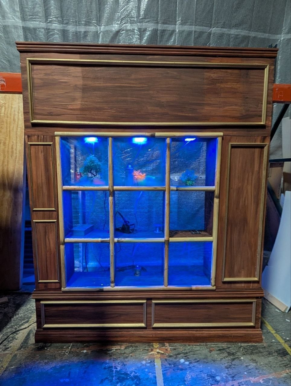
Cross-Pollination cabinet.
Identity & readiness
| Field | Value |
|---|---|
| Device class | cross_pollination |
| Instances | cross_pollination_01 … _06 (6 cabinets, interchangeable) |
| Controllers | Arduino Mega (game brain) + ESP32 (show-network modem: passes the Mega's status up and commands down, no game logic) |
| Room | Laboratory |
| Instance identity | Set in Understudy (device name, e.g. "Cross-Pollination 1"), not on the Mega. No current firmware reads the 0–9 BCD thumbwheel from the original spec. |
| Spec status | Locked — the boss's own final design doc, received 2026-09-25 (Blackwood_Manor_Cross_Pollination_MASTER_TRIALS_1-5_LOCKED.docx), fully replaces the earlier family/stability/repair design |
| Status | Show firmware 1.10.1 (standard) and 1.10.1-u6 (unit 6), both compiled and registered in Understudy's firmware list on 2026-10-09. Flashing every unit to 1.10.1 is on Zach's to-do; the one unit on the show network (Cross-Pollination 1) last reported Mega firmware 1.9.4 (2026-10-12). Zach playtested unit 6 on 2026-10-09. |
| Open questions | Welcome audio (folder 08) is still not played by the game (attract loop vs. one-shot undecided). The idle-warning clip (folder 10) is a placeholder voice. Target stickers over the sensors: options drafted, not yet chosen. The analog Seed Station second phase is still unspecified. |
Firmware
Source: platform/tools/cross_pollination/cross_pollination.ino (it replaced
the old mega_dumb_slave.ino in late September; the audio still lives under
platform/tools/mega_dumb_slave/audio/). Builds and flashing go through
Understudy's firmware list, never by hand.
Latest firmware
| Image | Board target | Version | Notes |
|---|---|---|---|
Game brain, standard cabinets (cross_pollination.ino) | Arduino Mega 2560 | 1.10.1 |
Real 5-trial game, 9 hall sensors, 9 RGB squares, 9 blacklights, DFPlayer audio, random 1-of-3 Hybrid Index ending. ~51 KB flash, 53% RAM. Registered in Understudy 2026-10-09. |
Game brain, unit 6 (same source, built with CP_UNIT=6) | Arduino Mega 2560 | 1.10.1-u6 |
Same game and lighting; unit 6's own answer key and clue timings. Use "Flash other firmware" → 1.10.1-u6 for unit 6 (not plain Update). Needs the unit-6 SD card. |
Show-network modem (device.ino, native Arduino) | ESP32 | arduino-0.19.1 (repo) |
Shared platform firmware. Its MEGA_LINK mode relays the Mega's status line up to Understudy and commands (including show standby/resume) down. Cross-Pollination 1's ESP32 currently reports arduino-0.17.0. |
What changed since the first bench build (plain language)
- Sensors you can trust (1.7.3–1.7.4): a touch has to hold for 50 ms over 3+ readings before it counts, so electrical glitches no longer play the game by themselves. The hall pins use the Mega's pull-up, so a loose sensor wire shows as a dead box instead of phantom touches. Every 10 s the unit prints how many glitches it filtered per box.
- Reset button (1.7.0, Mega pin 12): tap = reset the game; hold 2–6 s and release = box test on/off; hold 6 s = photo mode.
- Idle timeout: 60 s mid-game with no touch and no narration playing gives a warning (lights flash), then the game resets 30 s later.
- Attract look (1.9.2–1.9.3): at idle every square glows its own color (no two neighbours alike) with occasional tube-style flickers and slow color changes.
- Game look (1.9.5, 1.9.7): during the trials each box uses its own color; boxes nobody has picked are off, so a lit box clearly means something.
- Finale (1.9.4): a slow color glide across all nine boxes for the whole finale audio, then two white flashes, then back to idle.
- Show standby (1.8.0+): when Understudy sends standby (night mode / blackout) the cabinet stops the game and goes completely dark; resume returns it to a fresh idle.
- Photo mode (1.9.8–1.9.9): hold the reset button 6 s: every square full white, blacklights stay on, game and audio frozen, so each unit's real box colors can be photographed. Tap the button to leave.
- Trial 4 opening (1.10.0): on "Now examine the other specimens" the other six stay lit with the three broad leaves until "First, find the broad leaf" narrows back to the three.
- No accidental re-select (1.10.1): after a box is picked it ignores the wand for 1.5 s and until the wand has been lifted off it for a full second. Other boxes answer at once.
Build list / BOM — per cabinet (×6)
Supplier part numbers are Placeholder until sourcing is locked. Components and quantities below are real (from the working spec).
| Qty | Component | Role / notes | Supplier P/N |
|---|---|---|---|
| 1 | Arduino Mega 2560 | Local game brain — 9 digital sensor inputs, needs multiple hardware UARTs (Serial2 for DFPlayer) | PH |
| 1 | ESP32 | Show-network modem (Mega Serial1) | PH |
| 9 | Digital Hall-effect sensors (A3144-family) | To Mega digital pins 22–38 (even); shared 5 V + GND | PH |
| 9 | 8×8 addressable RGB matrices (WS2812B/WS2815) | 576 px; 3 chains of 3 boxes each, one data pin per chain | PH |
| 9 | UV / blacklight zones | Independent PWM channels, Mega pins 2–10 | PH |
| 3 | 4-channel MOSFET PWM boards | 9 UV channels used | PH |
| 1 | Magnetic wand | No electronics | PH |
| 1 | DFPlayer Mini / YX5200 + microSD | Semantic cues → tracks, Mega Serial2 @ 9600 baud | PH |
| 1 | Passive or powered speaker + 5-pin 3.5mm jack breakout | Bench-confirmed working, 2026-09-25 — see Wiring below | PH |
| 1 | Regulated 5 V supply | Electronics + RGB (parallel injection) | PH |
| 1 | 12 V UV supply | Subject to tape verification | PH |
| 1 | Reset button | Mega pin 12 to GND (tap / hold functions, see Firmware) | PH |
Wiring & service diagram / harness
Mega pin map (checked against cross_pollination.ino 1.10.1, 2026-10-12)
| Function | Mega pins | Notes |
|---|---|---|
| ARGB matrix chains | 44, 45, 46 | 3 independent chains, 3 boxes each (chain 0 = boxes 1–3, chain 1 = boxes 4–6, chain 2 = boxes 7–9) |
| Blacklight zones | 2–10 | 9 PWM zones, one per box |
| Reset button | 12 (to GND) | Tap = reset, hold 2–6 s = box test, hold 6 s = photo mode |
| Hall sensors (9 digital) | 22, 24, 26, 28, 30, 32, 34, 36, 38 | Box 1 = pin 22 (lowest), ascending to box 9 = pin 38 |
| DFPlayer Mini | 16 (TX2) / 17 (RX2) | Serial2 hardware UART, 9600 baud |
| ESP32 modem | 18 (TX1) / 19 (RX1) | Serial1: status up, commands down. Wiring and protocol: platform/tools/device/SWITCH-NODES.md ("Mega modem") |
Hall sensor / box numbering (real — 9 digital sensors, one per box)
Box numbering: front view, top-left = box 1, reading left-to-right then top-to-bottom — box 1 is always the lowest Mega pin number.
Box 1 (pin 22) | Box 2 (pin 24) | Box 3 (pin 26)
Box 4 (pin 28) | Box 5 (pin 30) | Box 6 (pin 32)
Box 7 (pin 34) | Box 8 (pin 36) | Box 9 (pin 38)
RGB: three data chains, one per box-row (1–3 / 4–6 / 7–9), each chain a 3-panel daisy-chain on its own Mega pin; distribute 5 V in parallel — never rely on matrix-to-matrix power transfer. Common ground with the controller.
The firmware reverses all 3 chains:
matrixChainReversed[] = {true, true, true}. For every chain, wire the daisy-chain
with the higher-numbered box's panel first and the lower-numbered box's
panel last (e.g. chain 0: box 3's panel first, box 1's panel last; the middle box in each
chain — 2, 5, 8 — is unaffected either way).
Real provenance, so you know how much to trust each one: chain 0 (boxes 1–3) and chain 2 (boxes 7–9) were directly, live-verified on 2026-09-25 — a solid-color test per panel with Zach reading off which physical box lit which color, confirming the swap in both cases. Chain 1 (boxes 4–6) was not independently tested (wasn't lit during that session) — it's reversed in firmware only by inference from the identical hardware/wiring pattern on the other two chains. If you're wiring boxes 4–6, this is the one to double-check with the same direct per-panel color test before trusting it blind.
Separately, if a panel doesn't light at all (not wrong box, just nothing): before suspecting firmware, check the panel's own DIN/DOUT — this exact symptom on this exact project was once traced to DIN/DOUT wired backwards on a hand-soldered panel (data going into the panel's OUTPUT pin, not its input). The two pins often look identical on cheap panel silkscreen; worth confirming with the panel's own datasheet/labeling before assuming a deeper problem.
Audio output jack (5-pin 3.5mm breakout)
Real, bench-confirmed: DFPlayer's audio output → jack pin 2 only. No separate ground wire needed — the speaker gets ground through its own USB power connection. Confirmed working live, 2026-09-25.
Game logic
Real 5-trial state machine. Full trial-by-trial box sequence and answers (standard cabinets and unit 6): Player Test Guide.
State machine
IDLE (attract look) → TRIAL_1 (pair) → TRIAL_2 (set of 3) → TRIAL_3 (stages A → B)
→ TRIAL_4 (3× donor→recipient) → TRIAL_5 (fixed 4-step sequence)
→ FINALE → HYBRID_INDEX (random 1 of 3) → IDLE
- Idle (attract): blacklights on, every square glowing its own color with tube-style flickers. The first valid wand touch on any box starts play (that touch is not an answer); the squares flicker on in twitching colors and Trial 1 begins.
- During the trials, unpicked boxes are off; the narration blinks the boxes it talks about (timed to the words), and a correct answer flashes only the correct boxes (square and blacklight together). Blacklights stay on.
- Each trial has its own correct/incorrect cues and a wrong touch never clears progress already made. Trial 3 is two stages (A, B); Stage C was removed for good in 1.9.0 because its lines were never recorded.
- Trial 5's 4th correct touch starts the finale: a color glide across all nine boxes during the finale audio, two white flashes, then one of 3 Hybrid Index endings at random, announced by audio. Then back to idle.
- Idle timeout, reset button, show standby and photo mode: see Firmware above.
The full light rules Zach set on site (and any rebuild of the light logic must
keep) are in GAME-INFO.md. Source of truth:
platform/tools/cross_pollination/cross_pollination.ino.
Media manifest
Folders on the show SD card (DFPlayer numbering). The script of every clip:
platform/tools/mega_dumb_slave/audio/sd-card-root/AUDIO_SCRIPT.md; the
per-track mapping: TRIAL_AUDIO_MAPPING.md in the same folder.
| Folder | Content | Status |
|---|---|---|
| 01 | "Box 1" … "Box 9" (used only by the box test) | On every official card |
| 02 | Trial 1 cues | Transcribed |
| 03 | Trial 2 cues | Transcribed |
| 04 | Trial 3 cues | Transcribed 2026-09-27 (Stage C lines were never recorded, so Stage C is not played) |
| 05 | Trial 4 cues | Transcribed; firmware remapped to the transcript |
| 06 | Trial 5 cues | Transcribed |
| 07 | Hybrid Index endings (3 tracks) | Transcribed |
| 08 | Welcome (40.0s) | On the card, not played by the game yet (trigger point undecided) |
| 10 | Idle warning ("will reset in 30 seconds") | Placeholder voice until the real recording exists |
Official SD cards
Five official standard cards (#1–#5, made 2026-09-30 to 2026-10-03) were written with
provision_sd_card.sh and every file checked against the repo (57 files each). The
register is platform/tools/cross_pollination/official-sd-cards.md. A card without
folder 01 or 10 is an old-layout card: the box test will be silent on it.
Unit 6 needs its own card: Understudy audio set
cross-pollination-sd-u6, version u6-2026-10-09-lavender (clues re-voiced for
what is really in its boxes, e.g. "orange fronds", the lavender in box 6). A standard card in unit 6,
or the unit-6 card in a standard cabinet, gives clues that don't match the boxes.
Show-control / tunable values (future)
| Parameter | Target | Range | Default |
|---|---|---|---|
| rgb_brightness PH | RGB matrices | 0–255 | 180 |
| uv_hold_ms PH | UV zones | 0–10000 | 3000 |
| success_volume PH | DFPlayer | 0–30 | 22 |
Open items
- Flash every unit to 1.10.1 (unit 6: "Flash other firmware" → 1.10.1-u6) through Understudy.
- Photo-mode photos of each unit, so the other cabinets' clues and colors can be checked against their real boxes the way unit 6 was.
- Target stickers over the hall sensors: options A–E drafted in
print/targets/(compare-v2.html), not yet chosen; the narration may then mention the target. - Ceiling lights above the cabinets (Zach's 2026-10-10 list).
- Decide the Welcome clip's (folder 08) trigger point; record the real idle-warning clip (folder 10).
- Confirm the boxes 4–6 chain order with a per-panel color test (inferred, see Wiring).
Open design item: the analog Seed Station second phase (Field Guide, worksheet, capsule) is not yet specified electronically.
Photos of unit 6's nine boxes and the script review against them:
boxes/README.md.